Based out of Melbourne Australia and Indiana USA, we blend hand crafted techniques with modern engineering to deliver articulate feature rich high-gain amplifiers.
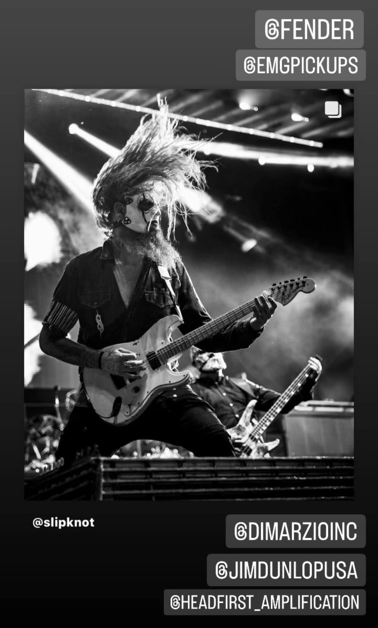
Jim Root
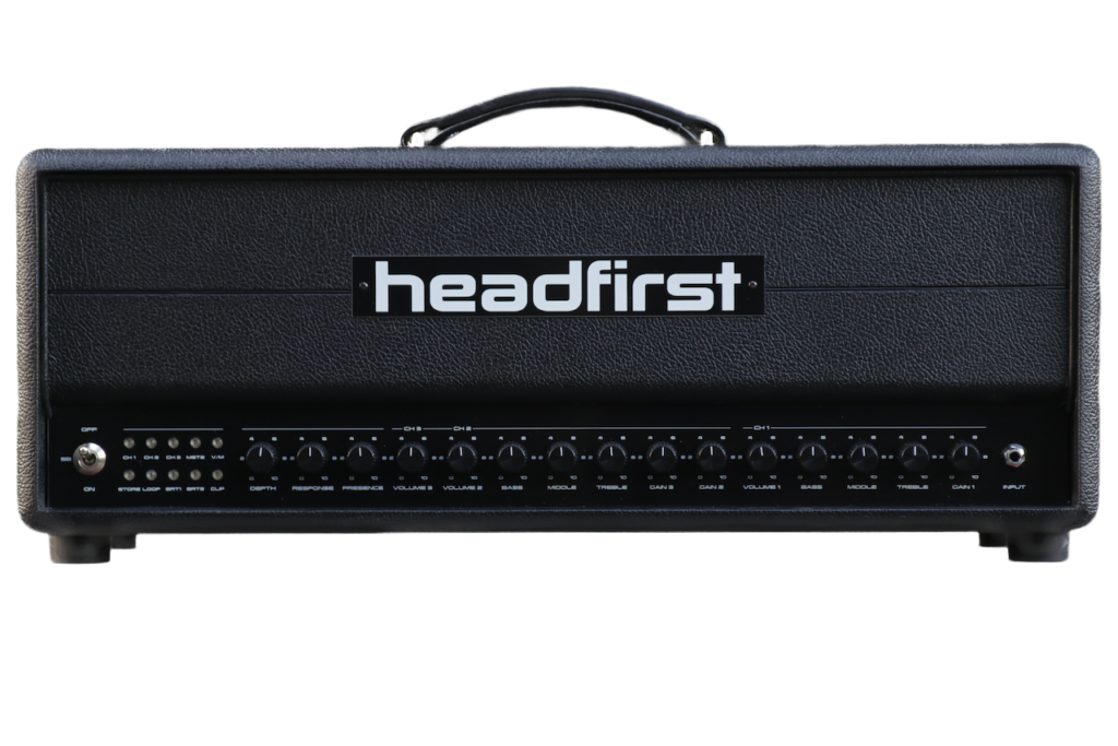
The Alta 100
“The Alta100 sounds VERY good…and the clarity of this amp is so genuine…it’s really a great amp, nice and articulate. I don’t know why I haven’t been using it the whole run, its awesome! Sounds so damn good, these are now the main heads in my live rigs”
Jim Root, SLIPKNOT
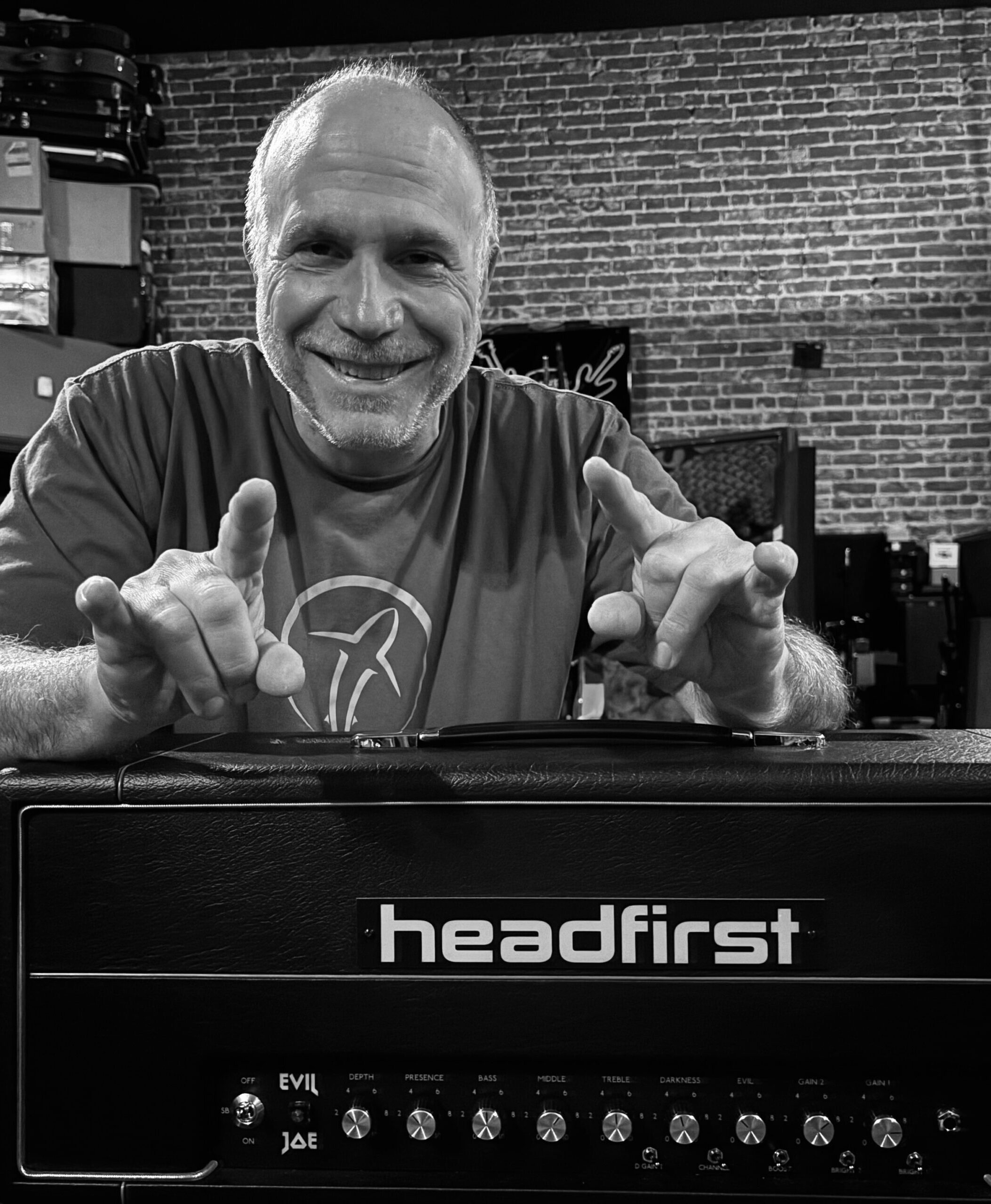
Evil Joe Barresi
The Evil Joe
“This Evil Joe amp has so many cool features, yet its simple to dial in a great sound instantly. Cascading gain stages with bright switches for clarity, diode and clipping choices, and a switchable gain boost to kick it into high gear. And even with all that gain it responds to your touch and volume control like an old school amp. Exceptional”
Joe Barresi, PRODUCER
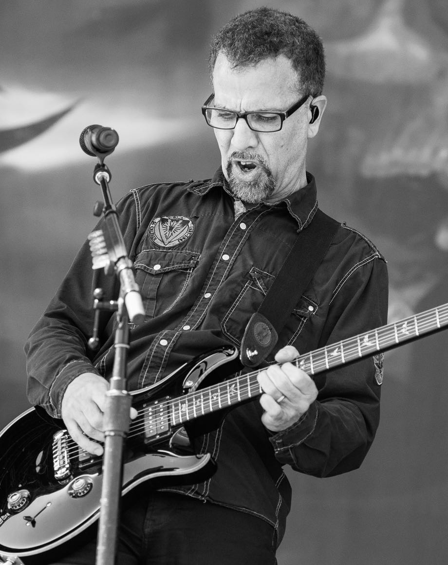
Tony Rombola
The Alta 100
“This amp rules! Killer tones with so much flexibility and control. Nothing not to like, love all the features, great job on this. Thank you, Tony.”
Tony Rombola, GODSMACK
Headfirst Amplification LLC, a US registered company, is proudly distributed and supported in the United States by Shea and team at Monomyth Amplification, Indiana.